 The gravure press has been a popular printing tool for a long time. Although it is no longer used in some printing sectors, it is still quite widely used in others such as commercial printing of magazines, label printing and corrugated packaging. Optima is well familiar with the working principles of a gravure press and has been involved in several press upgrade projects over the years.
Read full descriptions of two projects here:
Gravure press unwind unit upgradeUnwind unit
Functional details
Machine Power Up Unwind Diameter Check
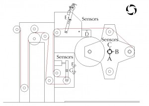
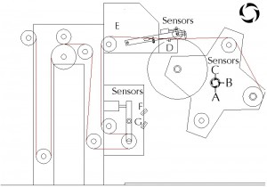
From power up of the machine the turret arc position sensor, Sensor “A”, which is shown on the diagrams below, determines selection of the running spindle. The line is not permitted to run until the reel size has been checked. To do this the unwind should be turned on which in turn tensions up the running reel by driving the spindle until the dancer positions to the centre of its range. On pressing the prepare button the turret drives the tensioned reel back to the test position where the reel diameter is checked by the ultrasonic diameter sensor, Sensor “F”. The size of the reel is then fed into the running spindle drive. From this point the unwind runs in normal operation.
Semi Automatic Splicing (Manual)
For splice operation to take place the incoming reel must be loaded and prepared leaving enough time for the semi automatic reel splice sequence to take place. Splice reflective tape should be placed on the reel so that it lines up with the joint position on the incoming reel and also in line with the splice joint detector laterally across the machine.
On pressing the prepare pushbutton on the unwind operator console the reel automatically turrets under at a high speed until it meets the almost at test position sensor, Sensor “B”, at which point the turret speed is reduced. The turret carries on rotating at a slow RPM until it reaches the at test position sensor, Sensor “C”, at this point it stops. The ultrasonic diameter sensor then measures the size of the reel and the size is transmitted to the incoming spindle drive.
The next part of the sequence starts the reel rotating at about 15 rpm. Then the splice detection sensor, Sensor “G”, detects the splice position on the incoming reel. Once detection is confirmed the reel rotates to the reel splice position. The position is detected by a through beam sensor, Sensor “D”, as shown on diagrams below. Once in position the splice arm lowers down to the reel pre-bump position. Also the incoming spindle accelerates up to the reel surface line speed.
At this point the splice pushbutton flashes rapidly indicating that the reel is ready to splice and is waiting for the operator to press the splice button. When the operator presses the splice button the PLC waits until it detects the angle where it should fire the bump roller. Once fired the bump roller presses down on the outgoing web making surface contact with the incoming reel. The next step in the sequence is when the PLC detects that the incoming reel is at the splice position at which time it fires the blade forward cutting through the web of the outgoing reel.
Once the cut has taken place the outgoing reel spindle is commanded to stop at a fast rate. At the same time the blade retracts, the splice arm returns to its parked position, and the incoming reel then is controlled via the unwind dancer. Note that at this stage the turret can be manually controlled to position the spindles as required.
Fully Automatic Splicing
For splice operation to take place the incoming reel must be loaded and prepared leaving enough time for the automatic reel splice sequence to take place. Splice reflective tape should be placed on the reel so that it lines up with the joint position on the incoming reel and also in line with the splice joint detector laterally across the machine.
The operator needs to enter two unwind diameter set points into the HMI. One is the sequence start diameter, which is the diameter of the outgoing reel at which the auto splice sequence starts. The second is the splice diameter, which is again the diameter of the outgoing reel at which the actual bump and cut takes place. These can only be determined by trials at set production speeds using the semi automatic mode of operation.
On pressing the prepare pushbutton on the unwind operator console the splice button starts to flash at a steady rate indicating the selection of the auto splice sequence. Once the outgoing reels diameter is equal to or less than the set start sequence diameter, the reel automatically turrets under at a high speed until it meets the almost at test position sensor, Sensor “B”, at which point the turret speed is reduced. The turret carries on rotating at a slow RPM until it reaches the at test position sensor, Sensor “C”, at this point it stops. The ultrasonic diameter sensor then measures the size of the reel and the size is transmitted to the incoming spindle drive.
The next part of the sequence starts the reel rotating at about 15 rpm. Then the splice detection sensor, Sensor “G”, detects the splice position on the incoming reel. Once detection is confirmed the reel rotates to the reel splice position. The position is detected by a through beam sensor, Sensor “D”, as shown on diagram section 7.2. Once in position the splice arm lowers down to the reel pre-bump position. Also the incoming spindle accelerates up to the reel surface line speed.
At this point the splice pushbutton flashes rapidly indicating that the reel is ready to splice. When the outgoing reels diameter is equal to or less than the set splice diameter, or the operator presses the splice pushbutton, the PLC waits until it detects the angle where it should fire the bump roller. Once fired the bump roller presses down on the outgoing web making surface contact with the incoming reel. The next step in the sequence is when the PLC detects that the incoming reel is at the splice position at which time it fires the blade forward cutting through the web of the outgoing reel.
Once the cut has taken place the outgoing reel spindle is commanded to stop at a fast rate. At the same time the blade retracts, the splice arm return to its parked position, and the incoming reel then be controlled via the unwind dancer. Note at this stage the turret can be manually controlled to the required position.
Note at any time during this sequence, the sequence can be cancelled by pressing the sequence cancel pushbutton on the unwind operator console. Note that to restart the sequence the incoming reel turret needs to be position in the reel load position.
 Control system details
Unwind Dancer Unit
The unwind unit was mechanically modified to accept a web dancer roller unit. This unit was designed to allow the maximum web accumulation possible in the area where the present unwind loadcell was located. This unit was to facilitate web storage due the variations in web tension and surface speed seen during a reel-to-reel splice on centre winding equipment. This unit contained the following equipment.
· Moving roller assembly · Pneumatic cylinders to generate web tension · Pneumatic E-P valve for pressure regulation · Dancer position feedback · Where required safety guarding of new moving equipment · Field wiring between control enclosures and field components (as covered in separate budget price) Included with this equipment was all mechanical installation and local termination of electrical control equipment.
Unwind Reel Check Position Sensors
Two proximity sensors were mounted on the unwind turret shaft to detect that the turret was in the correct position for diameter measurement and detection of incoming reel splice joint position. There were two sensors flags for each unwind spindle.
Unwind Reel Diameter Sensor
An ultrasonic distance sensor was installed to measure the incoming reel diameter for speed matching.
Splice Tape Detection Sensor
A sensor was installed which detect special reflective tape. This tape was positioned on the incoming reels splice point.
Unwind Shaft Encoder Counter Card
A High Speed Counter Module was added to the existing Melsec Q series PLC rack in the main control panel. To facilitate this, the following components were supplied.
· 2 channel high speed counter module · 3-way extension base unit · Extension base unit cable · Extension base unit PSU if required Unwind Pneumatic Panel Modifications
Modification to the control circuit of the unwind pneumatics panel was required to allow the bump roller and knife pneumatic valves to interface with new control equipment in the main panel.
Unwind Turret Speed Control Inverter
An inverter drive was fitted to the unwind turret motor to allow precise positioning of the incoming reel for both reel check position and final splice position.
To facilitate this the following components were supplied.
· 3 Phase V/F inverter drive · Drive supply protection · Drive output contactors · PLC IO control equipment Included with all equipment was full mechanical installation and local termination of new electrical control equipment. Also,
· Field wiring between control enclosures and field components. · Safety guarding where required of new moving equipment.
Gravure press rewind unit upgrade
Gravure press rewind unit upgrade
Functional Details
Machine Power up Rewind Diameter Check
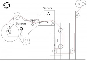
From power up of the machine the turret arc position sensor, Sensor “B”, which is shown on the diagram below, determines selection of the running spindle. The line is not permitted to run until the reel size has been checked. To do this the rewind should be turned off and the running reel diameter physically measured. This diameter is then be entered into the system via the HMI on the main line operator console. Once the diameter is entered, the rewind can be turned back on which tensions up the running reel by driving the spindle till the dancer positions to the centre of its range. The turret should then be rotated manual till the reel is in the required running position. If lay-on pressure is required then the running position will be the reel splice position.
Reel Lay-On Roller Operation
The lay-on roller can be raised and lowered at any time when the auto splice sequence is not in operation. For the lay-on roller to be lowered the turret should be in a splice position. This position is determined by either Sensor “C” when using 6” cores or Sensor “D” when using 3” cores. Note: for operation of the turret the splice arm should be in the parked position detected by Sensor “A”.
Manual Splicing
For splicing to take place the new core must be loaded in time for the turret rotation and splice cut to take place.
On pressing the turret under pushbutton the core rotates under till it reaches the splice position. This position is determined by either Sensor “C” when using 6” cores or Sensor “D” when using 3” cores. At this point the turret stops even if the turret under pushbutton is held on. To further turret in the same direction the turret pushbutton must be released and re-applied.
Once in this position on pressing the splice prepare pushbutton the core accelerates up to line speed and the splice arm lowers to the pre-spice bump position. Note: at this point that the lay-on back pressure valve be off to allow full bump pressure. On reaching line speed the splice pushbutton flashes rapidly indicating the core and rewind are ready for splice.
When the operator presses the splice pushbutton the bump roller fires on first for a short period of time followed by the blade. Just after the cut the outgoing reel spindle is decelerated to zero speed as quickly as possible and at the same time the blade retract. Also just after the cut the back-pressure lay-on valve is energised to place the bump roller in lay-on mode.
Automatic Splicing
For splicing to take place the new core must be loaded in time for the turret rotation and splice cut to take place.
The operator needs to enter two rewind diameter set points into the HMI. One is the sequence start diameter, which is the diameter of the outgoing reel at which the auto splice sequence start. The second is the splice diameter, which is again the diameter of the outgoing reel at which the actual bump and cut take place. These can only be determined by trials at set production speeds using the manual mode of operation.
After the core is prepared the operator presses the prepare pushbutton on the main line operator console. On pressing this pushbutton the splice pushbutton flashes at a steady state to indicate the automatic sequence is selected. Once the outgoing reels diameter is equal or greater than the auto splice sequence start diameter, if not retracted the splice arm be driven back into its parked position. The core then rotates under till it reaches the splice position. This position is determined by either Sensor “C” when using 6” cores or Sensor “D” when using 3” cores.
Once in this position the core accelerates up to line speed and the splice arm lowers to the pre-spice bump position. Note: at this point that the lay-on back pressure valve be off to allow full bump pressure. On reaching line speed the splice pushbutton flashes rapidly indicating the core and rewind are ready for splice.
Once the outgoing reels diameter is equal or greater than the splice sequence diameter or the operator presses the splice pushbutton, the bump roller fire on first for a short period of time followed by the blade. Just after the cut the outgoing reel spindle is decelerated to zero speed as quickly as possible and at the same time the blade retract. Also just after the cut the back-pressure lay-on valve is energised to place the bump roller in lay-on mode.
Note: at any time during this sequence, the sequence can be cancelled by pressing the sequence cancel pushbutton on the main line operator console. Note that to restart the sequence the incoming reel shaft needs to be position in the reel load position.
 Control system details
Rewind Dancer Unit
The Rewind unit was mechanically modified to accept a web dancer roller unit. This unit was designed to allow the maximum web accumulation possible in the area where the present rewind loadcell was located. This unit was to facilitate web storage due the variations in web tension and surface speed seen during a reel-to-core splice on centre winding equipment. This unit contained the following equipment.
· Moving roller assembly · Pneumatic cylinders to generate web tension · Pneumatic E-P valve for pressure regulation · Dancer position feedback · Where required safety guarding of moving equipment
Rewind Turret Positioning Sensor Flags
There were two sensors correctly mounted into the frame of the rewind unit that detect individually that each shaft was in the required position for splice to a 3” core. Four new flags were manufactured to allow detection of splice position for 3” and 6” cores on both shafts.
Unwind & Rewind Dancer Tension Signal
Each of the new dancer unit had an E-P valve for pressure regulation. The PLC was extended by including a new analogue output card. This was to facilitate the required pressure signal to the E-P Valves.
Drive Component Enclosure
From the site survey the following issues were discovered which in both cases needed new components to rectify.
· Safe stopping of AC drives · Drives DC bus interconnection
The required components needed to rectify the above two issues would not fit in the existing cubicle space. Thus an enclosure was supplied that was fixed to the drive end of the existing main control panel to carry all these components and the required wiring and containment. Included with all equipment was full mechanical installation and local termination of new electrical control equipment. Also, · Field wiring between control enclosures and field components · Safety guarding where required of new moving equipment
Would you like to know more about other control system projects we have completed on gravure press machines? Please, email us at info@optimacs.com or call us on +44 (0)1254 27 28 29

